Introduction
The Arduino has many uses, one of the more popular uses is with temperature sensors. For this the Dallas Onewire DS18B20 is most used. In this example we use this onewire chip and make a sketch for reading the temperature.
With this sensor you can get the temperature in any place like your room, car, etc.
Product
As in the past the temperature sensor output is analog, we need to add additional A/D and D/A chip for conversion. The new DS18B20 Temperature Sensor Module is a good solution for this, it use a unique bus line and economic package that make this sensor a good DIY component,
Specifications
- the module uses a single-bus digital temperature sensor DS18B20, the external power supply voltage Range is 3.0 V to 5.5 V, No standby power. Measurement temperature range of -55 ° C to +125 ℃, Fahrenheit equivalent 67 ° F to 257 ° F, -10 °C to +85 ° C range accuracy of ± 0.5 ° C.
- the temperature sensor is a programmable resolution of 9 to 12 temperature conversion to 12-bit digital format With a maximum of 750 milliseconds formula User definable nonvolatile temperature alarm settings.
- Each DS18B20 contains a unique serial number, you can use muliple ds18b20s in a bus. Temperature sensor can be placed at different places in the detected temperature.
Notes
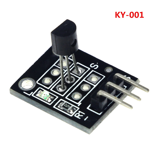
- The DS18B20 and ordinary transistors look similiar, so be careful not to regard it as a generalPass transistor to avoid damage.
- In order to prevent damage to the DS18B20 ensure that the powerLine and ground are not reversed.
- The relevant technical data on the bus did not mention a single number that can be linked to how much DS18B20, But in practical applications probably not so many.
- There is a bus length limitation that should be taken in consideration when long-distance communications, consider bus distributed capacitance and resistance.
- Identify DS18B20 Temperature Sensor Module power line, ground, and data Line, power line and ground points connect to the Arduino test board +5 V, GND, Data bus connect to the digital port.
Raspberry pi 2
note about raspberry test:
both 5v and 3.3v setup as described around the links below are working.
when i was testing with my finger to elevate temperature, the ds18B20 stop working after few measurements. It seems to be dead and not viewable from the pi. After waiting a little bit, i powered off and on the pi and the sensor start to answer again. It’s perhaps it is a cheap module and the elevation speed too fast ?
- Simple tutorials that works for me on instructables
- Raspberry pi tutorial and details about KY001 can be found here .
Setting up
First edit /boot/config.txt and find ‘dtoverlay’ and replace with dtoverlay=w1-gpio
save and reboot
after reboot execute:
sudo modprobe w1-gpio
sudo modprobe w1_therm
ls -l /sys/bus/w1/devices/
from the output of the ls command, write down the unique number of your DS18B20 (like: 28-000006dfa76c)
write a python script like this one:
import time

try:
        while True:
                tempfile = open("/sys/bus/w1/devices/28-000006dfa76c/w1_slave")
                thetext = tempfile.read()
                tempfile.close()
                tempdata = thetext.split("\n")[1].split(" ")[9]
                temperature = float(tempdata[2:])
                temperature = temperature / 1000
                print temperature

                time.sleep(1)
except KeyboardInterrupt:
        pass
Connecting
- 3.3V from the sensor to the 3.3V rail on your raspberry pi
- GND to the GND rail on your raspberry pi
- Data to a pin 7 / GPIO04 on the raspberry pi
- Connect your resistor with the 3.3v and the Data