Buy the 37 in 1 kit at Amazon
Contents
Use
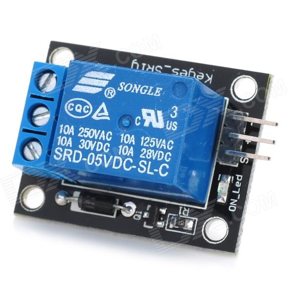
The company produces relay module can be connected to 240V AC or 28V DC power into a variety of other electrical parts. The relay can be used in anti-theft alarm, toys, etc. Relay is an electrically controlled device. It has a control system (also known as the input circuit) and the control system (Also known as the output circuit).
Commonly used in automation control circuit, it is actually a small Current to control a large current operation “automatic switch.” Therefore, the circuit automatically adjusts the play, safety protection, transfer Conversion circuit and so on. Particularly suitable for single-chip control strong electric devices. In the control and use is also very convenient, just give input corresponding output relay different levels, you can Achieved by controlling the relay control purposes other devices, in addition, in the multi-channel relay PCB layout on the use of two lines Layout, user-lead connections. While in the circuit of a DC diode added greatly improved relay
Module to engage current ability to prevent the transistor being burned. In addition, we added a relay this power indicator Lights (except relay all the way), the indicator is red. In brightest relay also adds a status indicator.
Specifications
- the main purpose Relay is a function of the automatic isolation switching elements, are widely used in remote control, telemetry, communications, automatic control, Mechatronics and power electronic devices, is one of the most important control elements. Boils down to the following effect:
- expand the control range: for example, multi-contact relay control signal reaches a certain value, you can not press the contact group Different forms, and for access, breaking, connected multi-channel circuits.
- Zoom: for example, sensitive relays, relays, etc., with a very small amount of control, you can control a large The power of the circuit.
- Integrated signal: for example, when a plurality of control signals in the form prescribed input multi-winding relay, by comparison mechanized Together, to achieve the desired control effect.
- automatic, remote control and monitoring: for example, the automatic device relays together with other appliances, can be composed of program control Wire line, in order to achieve automatic operation
- Note
- Rated voltage: refers to normal working hours relay coil voltage required, The control circuit is a control voltage. According to the relay model, can be ac Pressure, it can be a DC voltage.
- DC resistance: refers to the relay coil DC resistance, measured by the multimeter.
- Pick-up current: refers to the relay pull action can produce a minimum current. In normal use, the current will be given Be slightly larger than the pull current, so that the relay can be operated stably. The work of the coil voltage is applied, generally do not To more than 1.5 times the rated working voltage, otherwise it will have a greater current to the coil burnt.
- release current: refers to the relay generates the maximum current release action. When the relay state current is reduced to a Certain extent, the relay will revert to the release of unpowered state. Then the current is much smaller than the pull current.
- contact switch voltage and current: is the relay to allow the applied voltage and current. It determines the relay to control Voltage and current size, use can not exceed this value, it will be very easy to damage the relay contacts.
Schematic
- Arduino digital pin 10 –> module pin S
- Arduino GND –> module pin –
- Arduino +5V –> module pin +
Module test
Pin Description below Description: COM to VCC, NO then we have to control the LED anode, which Like when the relay turns on, LED lights will be lit; To complete the look of this test must be prepared to what what they specifically
- Arduino controller × 1
- USB data cable × 1
- 1 relay module × 1
- Led indicator × 1
- The resistance of the resistance 330 × 1
Of course, we have the following physical connections for a specific reference
Example Code
//KY019 5V relay module
int relay = 10; // relay turns trigger signal - active high;
void setup ()
{
  pinMode (relay, OUTPUT); // Define port attribute is output;
}
void loop ()
{
  digitalWrite (relay, HIGH); // relay conduction;
  delay (1000);
  digitalWrite (relay, LOW); // relay switch is turned off;
  delay (1000);
}